24V 3-Phase PMSM Sensored Sinusoidal Drive (Stator-Mounted)
Description
A sensored SVPWM drive using low-cost general purpose ST STM32F030 MCU. Rotor position is detected using 3x TI DRV5013 hall sensors and sector is determined based on the reading of all three sensors. PCBA is mounted at stator and hall sensors positioned at rotor’s magnets’ location. Each hall sensor is connected to a GPIO and set up to generate interrupt on level changes. Rotor angle is interpolated using rotor speed derived from interval between hall sensor interrupts.
SVPWM waveform for motor control is computed base on AVR32710 application note1.
To speed up dx and dy calculation, a sine LUT for each degree from 0 to 90 was generated.
\(dx = \sin(\frac{\pi}{3}-\theta)\)
\(dy = \sin \theta\)
PWM duty cycles (Ta, Tb, Tc) for each period are then calculated for each sector:
| Sector | q | CCW | CW |
|---|---|---|---|
| 1 | \([0,\frac{\pi}{3}]\) | PWM0 = (T - dx - dy)/2 PWM1 = (T + dx - dy)/2 PWM2 = (T + dx + dy)/2 |
PWM0 = (T + dx + dy)/2 PWM1 = (T - dx - dy)/2 PWM2 = (T - dx + dy)/2 |
| 2 | \([\frac{\pi}{3},\frac{2\pi}{3}]\) | PWM0 = (T - dx + dy)/2 PWM1 = (T - dx - dy)/2 PWM2 = (T + dx + dy)/2 |
PWM0 = (T + dx + dy)/2 PWM1 = (T + dx - dy)/2 PWM2 = (T - dx - dy)/2 |
| 3 | \([\frac{2\pi}{3},\pi]\) | PWM0 = (T + dx + dy)/2 PWM1 = (T - dx - dy)/2 PWM2 = (T + dx - dy)/2 |
PWM0 = (T - dx + dy)/2 PWM1 = (T + dx + dy)/2 PWM2 = (T - dx - dy)/2 |
| 4 | \([{\pi},\frac{4\pi}{3}]\) | PWM0 = (T + dx + dy)/2 PWM1 = (T - dx + dy)/2 PWM2 = (T - dx + dy)/2 |
PWM0 = (T - dx - dy)/2 PWM1 = (T + dx + dy)/2 PWM2 = (T + dx - dy)/2 |
| 5 | \([\frac{4\pi}{3},\frac{5\pi}{3}]\) | PWM0 = (T + dx - dy)/2 PWM1 = (T + dx + dy)/2 PWM2 = (T - dx - dy)/2 |
PWM0 = (T - dx - dy)/2 PWM1 = (T - dx + dy)/2 PWM2 = (T + dx + dy)/2 |
| 6 | \([\frac{5\pi}{3},2\pi]\) | PWM0 = (T - dx - dy)/2 PWM1 = (T + dx + dy)/2 PWM2 = (T - dx + dy)/2 |
PWM0 = (T + dx - dy)/2 PWM1 = (T - dx - dy)/2 PWM2 = (T + dx + dy)/2 |
To keep cost low, linear regulator was used to step down input voltage to 3V3 and integrated pre-driver with VDS sensing OCP was used.
Project was halted before fully developed, with tasks such as speed feedback and control loop, and advance angle yet to be implemented.
Block Diagram

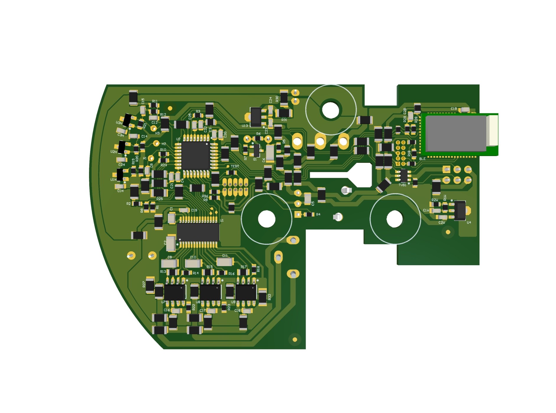
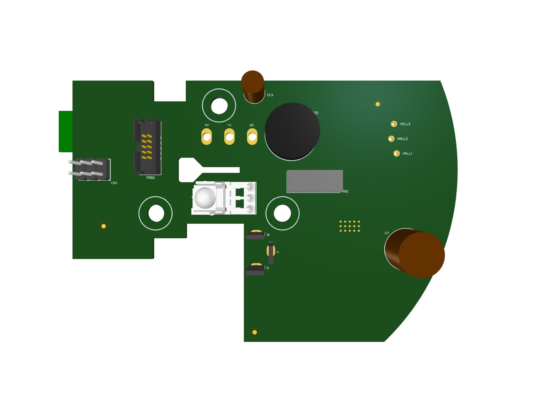
Gallery
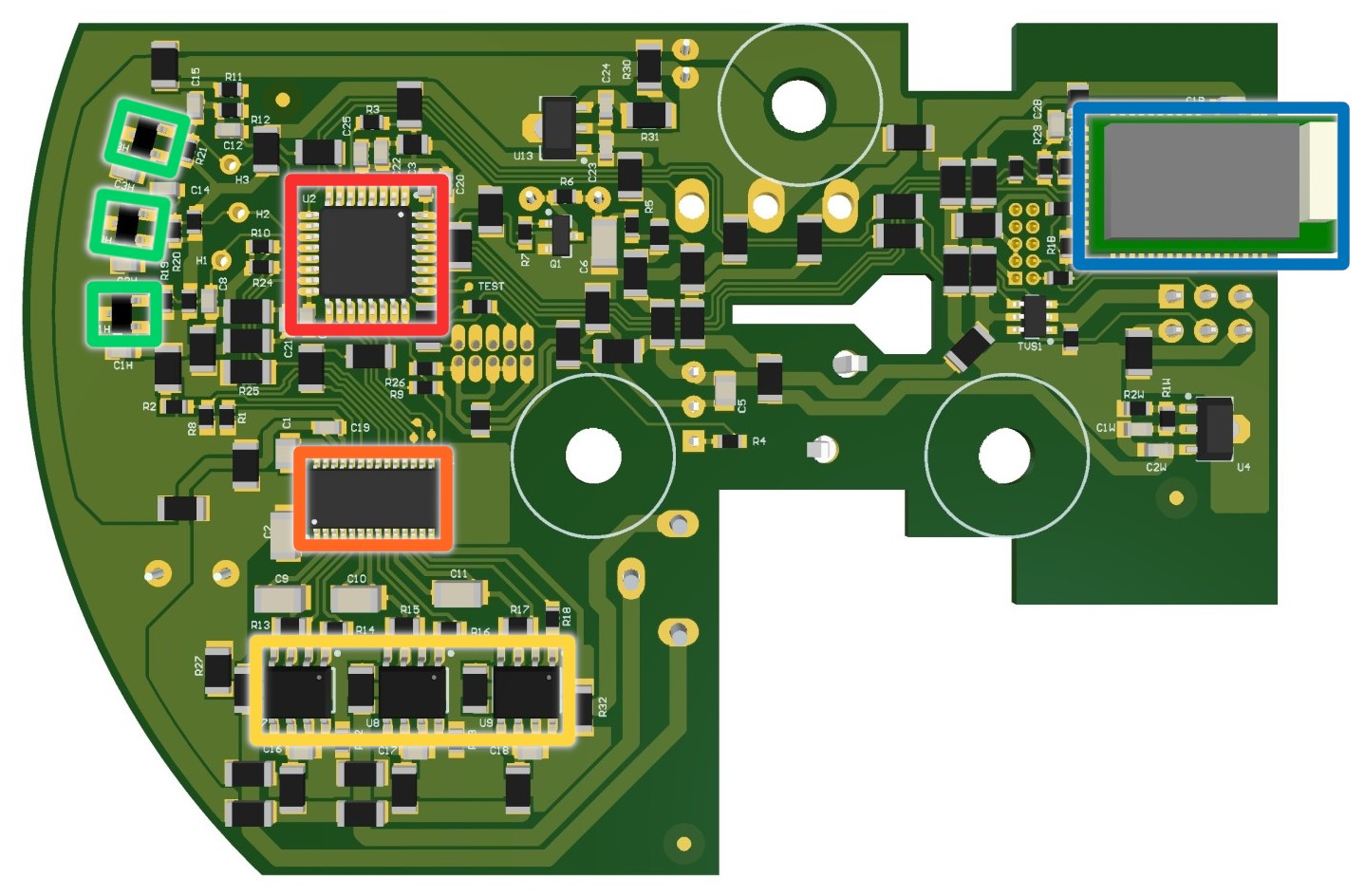
🔴ST STM32F030 48MHz ARM Cortex-M0 MCU
🟠MPS MP6529 35V 3-Phase BLDC Pre-Driver
🟡3x TI CSD88537ND 60V N-ch Power MOSFET
🟢TI DRV5013 38V Hall-Effect Latch
🔵Raytac MDBT40 BLE 4.2 module powered by Nordic nRF51822