24V/35W 3-Phase PMSM Sensorless FOC Drive with HRPWM
Description
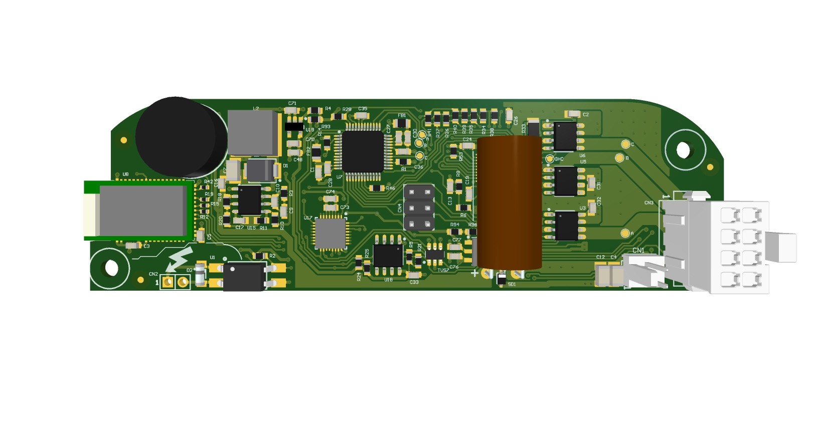
A ceiling fan controller which consists of an application MCU and a 3-phase inverter for driving PMSM motor, based on TI TMS320F28027F C2000 Piccolo real-time MCU, 65V TI DRV8323H smart gate driver, and 3x TI CSD88537ND Dual N-Channel Power MOSFET.
The high-efficiency inverter has a 3-shunt sensing topology and sensorless FOC control was implemented using TI‘s InstaSPIN-FOC. The highly integrated smart gate driver allowed the design to achieve very small board area with integrated CSA, adjustable gate drive source/sink current, and overcurrent monitors.
HRPWM
The nature of PWM switching of the inverter results in ripple current at the same frequency as the PWM frequency in the motor windings. On the other hand, the control granularity limited by the PWM resolution also results in a separate and lower frequency ripple current, which falls in audible range and more noticeable.
In some motors, the corresponding electromagnetic force related to the these ripple current would result in micro vibration and subsequently, undesired audible noise whenever PWM is switching.
As an entry-level InstaSPIN MCU, the F28027 has only 4 HRPWM channels while a 3-phase inverter needs to be controlled by 6 gate signals. With “3x PWM Mode”, the DRV8323 generates the complementary low side gate signal automatically and allowed the use of HRPWM functionality of the F28027 to enhance the PWM resolution. The table below shows how the PWM resolution improved with HRPWM (assuming typical MEP step size of 150ps):
| PWM Mode | CPU Clock (SYSCLK) |
PWM Freq. | Regular PWM (Resolution1 / Step Size) |
HRPWM (Resolution1 / Step Size) |
|---|---|---|---|---|
| Edge-aligned PWM | 60 MHz | 18 kHz | 11.7 bits / 16.67ns | 18.5 bits / 150ps |
| Center-aligned PWM | 60 MHz | 18 kHz | 10.7 bits / 33.33ns | 17.5 bits / 300ps |
From testing, it was observed that the lower frequency ripple current corresponding to the control granularity could be improved by ~5x measured on an oscilloscope when HRPWM was enabled. The reduction of the current ripple caused by the control error directly reduced the audible noise to a great extend.
Controller Function
The application MCU also served as system controller and carries the following roles:
- manages fan motor speed by commanding speed to motor MCU
- manages motor MCU low power state by holding reset line of motor MCU low to reduce standby power
- stores motor parameters and CSAs calibration value in on-chip EEPROM
- manages led lighting brightness by commanding brightness level to led driver daughter board
- receives IR commands from IR receiver from daughter board
- receives and decodes proprietary PLC commands from mains zero crossing detector
Though designed and optimized for 24V operation, the 65V smart gate drive and power MOSFET allows 48V operation with minor hardware changes.
Block Diagram

Gallery
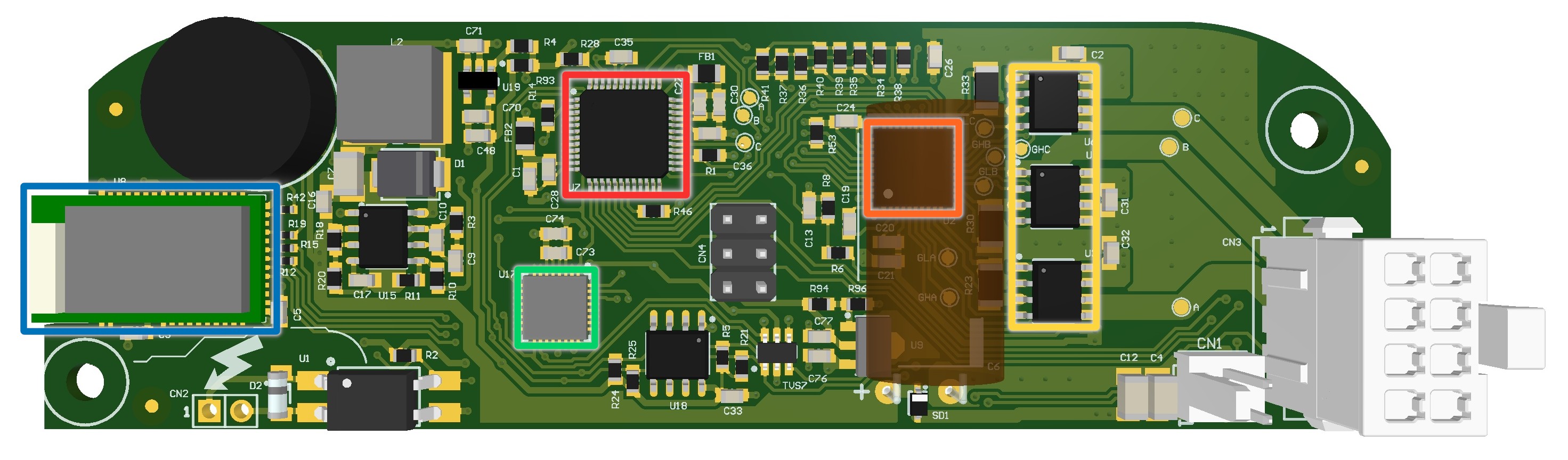
🔴TI TMS320F28027F 32-bit 60MHz MCU with InstaSPIN-FOC
🟠TI DRV8323H 65V 3-phase Smart Gate Driver with Current Shunt Amplifiers
🟡3x TI CSD88537ND 60V N-ch Power MOSFET
🟢NXP MKL02Z32VFM4 48MHz Ultra-low-power ARM Cortex-M0+ MCU
🔵Raytac MDBT40 BLE 4.2 module powered by Nordic nRF51822