High-Voltage 35W 3-Phase PMSM Sensorless FOC Drive + 16W LED Driver with Passive PFC
Description
Motor Drive
A 3-phase inverter for driving PMSM motor, based on TI TMS320F28027F C2000 Piccolo real-time MCU and 600V ST STGIPN3H60 SLLIMM-nano IPM. The inverter has a 3-shunt sensing topology and sensorless FOC control was implemented using TI‘s InstaSPIN-FOC. From testing, stable and quiet motor operating can be achieved by sensing the motor phase currents directly using ¼W resistors instead of signal amplification using op-amps for cost-saving.
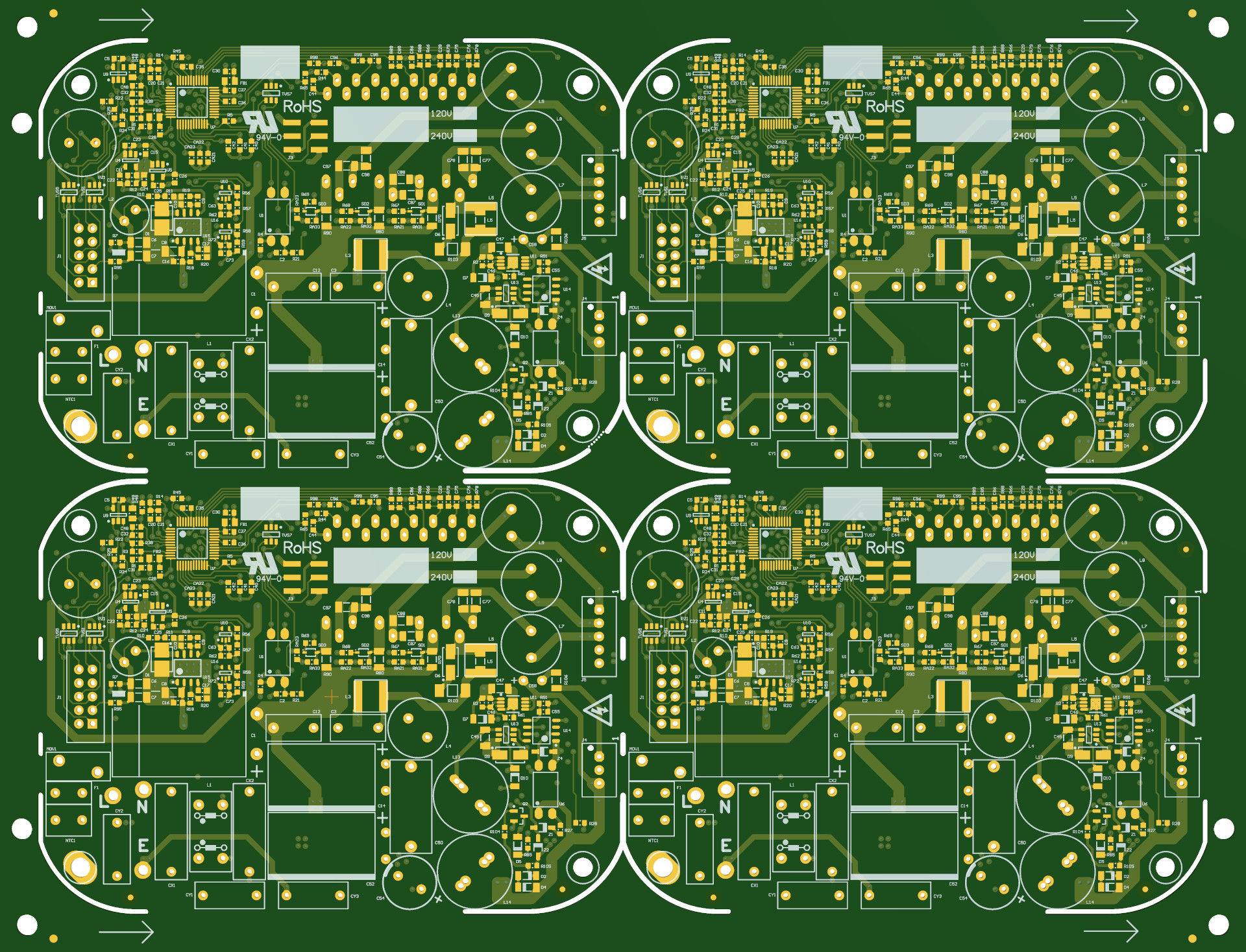
Two board variants sharing the same PCB layout were developed for 120VAC and 240VAC mains voltage countries, with different components values for motor phase current sense resistors, motor phase voltage feedback resistor dividers, DC bus capacitor, fuse and ICL.
LED Driver
The 20W constant-current LED driver is a non-isolated buck converter which consists of OnSemi FAN6604 PWM controller, Infineon IRS25752L high-side gate driver and 500V Infineon IPD50R650CE NMOS. The circuit is able to achieve 50:1 dimming ratio.
Some cost saving was achieved by using the same voltage output of range 18~24V for LED light to power the rest of the system thus only a single converter was needed. The converter was designed to output a minimum voltage of 18V at power-up when the feedback signal is zero (MCU not running and LED current is zero) and the LED strings was configured to make the total forward voltage above 18V before conducting so that they stay off while the converter continue switching and supplies 18V to system. Since there is a constant supply to the LED, the IR receiver circuit that resides on the LED panel is able to power from this supply and reduced the need of a dedicated wire for supply. For the voltage & current control, a filtered PWM signal from the MCU combines with the LED current provides the feedback signal to PWM controller.
PFC was realized cheaply using passively using voltage doubler rectifier since input power related to LED driving was <20W and PF requirement was not needed for motor operation.
Others
PCB was designed for wave solder for bottom side due to high THT components count, with solder thieving pads included, shadow effect prevented by design, and larger SMT land patterns were used.
The motor controller also served as system controller with the following roles:
- manages fan motor speed
- enters standby mode and running at lower clock speed to reduce standby power
- stores motor parameters and V/I offset values in FLASH
- manages led lighting brightness by adjusting PWM duty cycle to LED driver
- decodes IR commands from IR receiver from daughter board
- decodes proprietary PLC commands from mains zero crossing detector
Heat of STGIPN3H60 IPM, IPD50R650CE NMOS, freewheeling diode, and bridge rectifier is dissipated to an aluminum back-plate using Sil-pad.
Final PCBA size is 108 x 79.6 x 23.1mm1.
Block Diagram

Gallery
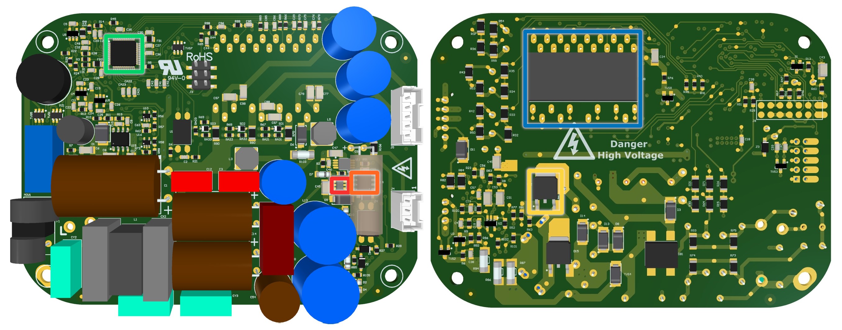
🔴Infineon IRS25752L 600V High-side Gate Driver
🟠OnSemi FAN6604 PWM Controller
🟡Infineon IPD50R650CE 500V N-ch MOSFET
🟢TI TMS320F28027F 32-bit 60MHz MCU with InstaSPIN-FOC
🔵ST STGIPN3H60 600V 3-phase IGBT Inverter Bridge SLLIMM-nano IPM
-
A-side=17.5mm, PCB thickness=1.6mm, B-side (STGIPN3H60)=4mm ↩