General-Purpose 24V PCBA FCT Tester
Description
The conception of a general-purpose, 24V PCBA FCT tester tied to the FCT requirement of assembled PCB for almost every project involved. When completed, the PCBA FCT tester would benefit the next projects onwards with its hardware & firmware reusability.
The tester was design with ease of maintenance in mind. As such, modular design approach was adapted for some core components to allow easy replacement in the event of failure. The NUCLEO-G070RB is pluggable and and DC-DC converter modules were used. It was planned to make more circuits into pluggable module in the next revision to to suits various product functions.
Plenty testing related circuits were incorporated in the design, fully utilizing all the pin-outs of the NUCLEO-G070RB.
- 24V/12V/5V voltage selection jumpers to supply to DUT
- High-side load switch using TI TPS1H100 with adjustable current limit to control power to DUT and limit inrush current during start-up or short-circuit conditions
- 2-channel bidirectional precise current sensing circuits using TI INA240 that can be flexibly wired to measure DUT currents such as operating/idle current or LED driver output current
- Programming signal isolation using TI TMUX1511PWR analog switches to achieve hardware isolation for accurate idle current measurement and prevent MCU reset problems
- 16-channel analog input with AD AD8244 precision FET input buffers (4-channel with 24V to 3V3 resistor divider to read 24V voltages)
- 3+1 USART channels with line buffers (3 when RS485 is used)
- 1x RS485 (half-duplex) using TI SN65HVD1780 with termination selection jumper
- Keypad interface using TI TCA8418 keypad scanner
- 11x digital output signal for LCD interface, with additional 5V trimpot for backlight adjustment
- 2x 1A SPDT relays for extra controls such as bypass or bleeder resistor connection
- 8x optocouplers I/O (depending on circuit configuration, can be 8in/8out/4in+4out
- 2x general-purpose 3V3 digital input
- 3x NPN LED driver for panel status LED
Final PCBA size is 130 x 130 x 23mm1.
Block Diagram

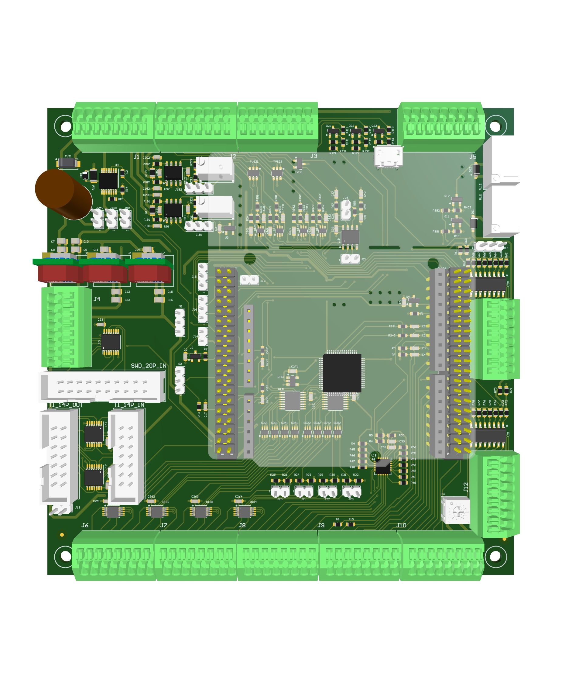
Gallery
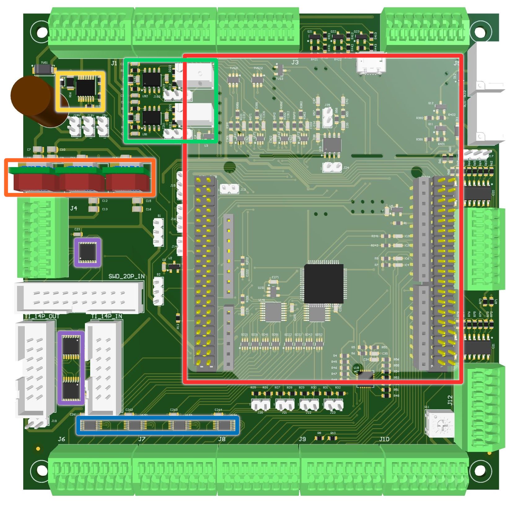
🔴STM32 NUCLEO-G070RB Nucleo-64 with STM32G070RB MCU
🟠Murata OKI-78SR 12V, 5V, 3v3 Outputs DC-DC Converters
🟡TI TPS1H100 40V High-Side Power Switch
🟢TI INA240 Ultra-Precise Current Sense Amplifier
🔵AD AD8244 Precision FET Input Buffer
🟣TI TMUX1511PWR Low Capacitance Analog Switch
-
A-Side (Box header=8.5mm, Nucleo PCB thickness=1.6mm, Nucleo box header=8.51mm): 18.61mm, PCB thickness=1.6mm, B-side=2.5mm ↩